Calculations were performed with both the deterministic Attila solver and MCNP® using Attila4MC (referred to herein as Attila4MC) CADIS variance reduction simulating one experimental configuration from “Shielding of Radiation Fields Generated by 252Cf in a Concrete Maze, Part I – Experiment” [1]. The 252Cf source (8.1E+10 neutrons s-1) was placed in the center of a single-legged concrete maze and a volume detector was placed at the maze opening. Dose rate results for neutron only and neutron-gamma simulations were generated for both Attila and Attila4MC. Results from CSG (constructed surface geometry) MCNP calculations using the source biasing inputs and weight windows from Attila4MC CADIS were also included.
Figure 1 illustrates the model geometry. The small volume source (yellow, intersection of green and red lines, right) is modeled as dry air. The single-legged maze walls, floor, and ceiling are Portland concrete (grey). The walls separate two dry air regions (blue). The volume detector at the maze opening (orange) is also comprised of dry air.
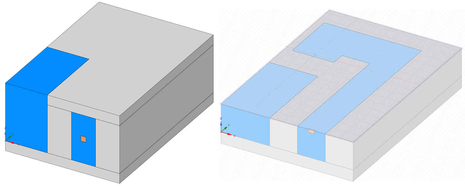
Figure 1. 3D model (left) and a XY-cross sectional cutout (right) of the problem geometry.
Material elemental compositions are listed in Table 1 with their corresponding densities. Compositions were taken from [2]. The Compendium identifiers are: concrete, Portland (#98) and air, dry (#4). Note that argon (Ar) is not included in the dry air material. This is due to no deterministic cross section data existing in the Fendl-2.1 library for Ar.

Table 1. Material Compositions by Weight Fraction (Wgt. Frac.) and Densities (g cm-3)
Figure 2 shows the XY-cross sectional view from Figure 1 with relevant measurements in cm.
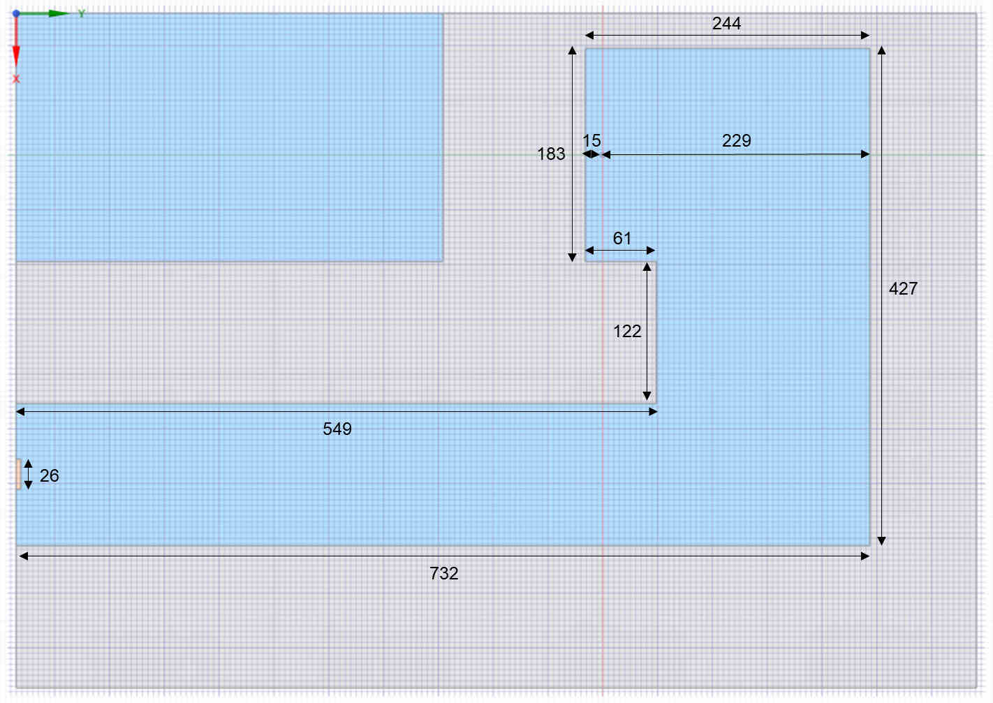
Figure 2. XZ-cross sectional view with relevant measurements (cm). R25 indicates a 25 cm curvature radius.
Dimensions reflect those reported in [1] with the exception of the thickness of the ceiling and floor. The values were not documented and assumed to be 50 cm. The extent boundaries of the model are 579 x 823.5 x 394 cm. The center of the small 2 x 2 x 2 cm source is 122 cm off of the floor and 15 cm from the maze wall in the (-) y-direction relative to the source. The distance from the center of the source to maze wall in the (+) y-direction is 229 cm. The height of the maze is 244 cm. The width of the terminal leg of the maze is 122 cm. The volume detector has approximate dimensions of 26 x 4 x 26 cm.
The Attila4MC and MCNP-CSG source is modeled as a uniformly distributed, isotropic volume source. The deterministic Attila solver calculations are performed using the First Scattered Distributed Source (FSDS) capability with a quartic ray tracing style to create a point source (minimum radius = 0.0001) located at the center of the volumetric source solid body. Note that no volumetric source was implemented in the deterministic Attila solver calculations. The 252Cf neutron source spectrum is modeled after the spectrum from [3], interpolated to 87 energy groups. The source strength is normalized to 8.1E+10 particles s-1.
Two separate solid body geometries, and consequently two separate meshes, were created for the deterministic Attila solver and Attila4MC calculations. The deterministic Attila solver geometry is identical to the information presented in the Problem Summary, with the exception that the maze walls were sliced into 10 cm segments along various axes as seen in Figure 3. This technique was implemented to enforce an anisotropic mesh maximum edge length in the desired direction while reducing the total number of elements in the computational mesh. The MCNP-CSG is identical to the model used for Attila4MC.
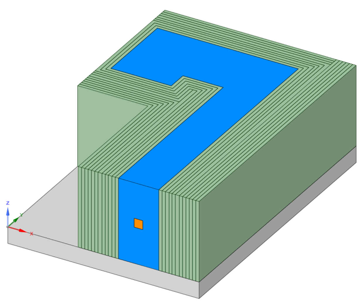
Figure 3. 3D model of the deterministic solver solid geometry with the ceiling and outer air removed for visualization purposes. The maze wall (green) is segmented into 10 cm slices along various axes.
The deterministic solver computational mesh contains 81,965 elements. A max allowable edge length was set to 50 cm and no local max edge lengths were applied to any Solid Regions except for the air inside the maze (InsideAir), which has a max edge length of 30 cm. The concrete maze wall was segmented before generating the mesh, imposing a 10 cm maximum mesh edge length in various directions throughout the maze. A Size Transition Factor of 0.00 was used. Curvature Refinement was not utilized. Anisotropic Mesh Sizing was enforced in the Z Direction for the Roof and Floor Attila Regions, resulting in Edge Lengths of 10 cm in the z-direction.
The Attila4MC computational mesh contains 39,568 elements. A max allowable edge length was set to 50 cm and no local max edge lengths were applied to any Solid Regions except for the air inside the maze (InsideAir), which has a max edge length of 30 cm. A Size Transition Factor of 1.00 was used. Curvature Refinement was not utilized.
Calculations use the FENDL-2.1 cross section set (175 neutron groups, 42 gamma groups). All neutron groups are assigned and collapsed by 5. All gamma groups are assigned and collapsed by 2, with the exception of neutron only calculations (all gamma groups unassigned). For the deterministic Attila solver calculations, an SN order of 16 and a Pn order of 3 are used. For the deterministic portion of the Attila4MC CADIS calculation, an SN order of 20 and a Pn order of 0 are used. The Triangular Chebychev Legendre quadrature is used for both calculation methods.
To calculate the dose rate in the volume detector, a response function was applied to the scalar flux with a Scale Factor of 10000 using the deterministic Attila solver, and the average particle flux (F4 tally) with a Tally Multiplier of 10000 are calculated using Attila4MC and MCNP-CSG. The calculated dose rates are in units of µSv hr-1. Table 2 shows which calculations provide results for the various methods employed. For the Neutron-Gamma calculations, the motivating tally was the gamma flux with response in the volume detector.

Table 2. Calculation File Index
A contour plot of the flux and relative error from the Attila4MC, Neutron-Gamma calculation is provided in Figure 4.
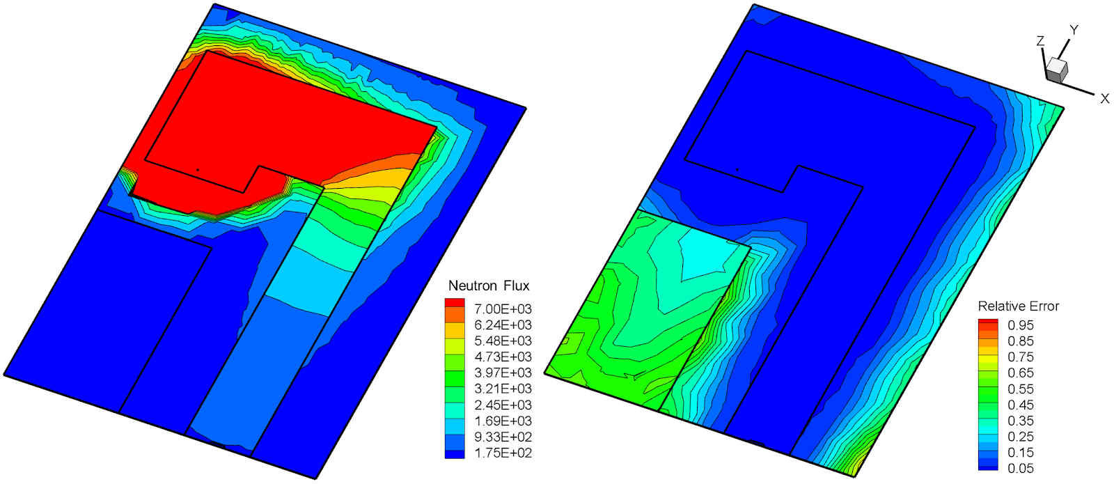
Figure 4. Contour plot of the neutron flux (left) on the Z-plane from the Attila4MC, Neutron-Gamma calculation.
Table 3 shows dose rate (µSv hr-1) results in the volume detector using Attila, Attila4MC, and MCNP-CSG. All calculations were run to convergence with a relative error of less than 7%. Neutron only calculations were run using 1.00E+07 histories and Neutron-Gamma calculations were run using 5.00E+07 histories. The results for a particle in the Neutron-Gamma calculations are underlined when that particle type’s results are reported in the table (i.e. Neutron-Gamma reports the neutron dose rate results). Ratios of Attila to Attila4MC (Attila/Attila4MC) results and MCNP-CSG to Attila4MC (MCNP/Attila4MC) results are included.
Table 3. Dose Rate Results (µSv hr-1) by Calculation Type and Detector Particle
The results are comparable to the experiment results from [1], in which dose rates of 14.1 and 1.75 were reported in Table 1 of the document for neutrons and gammas, respectively. The authors noted that the detector used in the experiment suffers from directional dependence and expected the measured dose rate to be less than the true values when thermal neutron fluence is high.
In both the Neutron and Neutron-Gamma calculation types for Attila4MC and MCNP-CSG, the neutron dose rate results are expected to be approximately equal. If the desired result is the neutron dose rate only, the most efficient approach is to run the neutron only model because the weight windows and source biasing are both optimized to obtain the neutron dose rate in the detector. For the Neutron-Gamma calculations, the motivating tally is the gamma dose rate, resulting in source biasing that is heavily weighted towards lower energies. Table 4 shows the results information (edit or tally number) for the output files associated with the results from Table 3.

Table 4. Edit and Tally Information for Calculation Method Results